
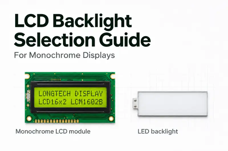
An LCD backlight is the light source behind a liquid crystal display. In a monochrome module, the LCD controls how much of that light reaches the viewer through each segment or pixel. For an industrial product, we select the backlight based on the viewing conditions, the available power, and the appearance of the display through the finished enclosure window.
Consider a control panel that looks bright on the bench. Once it sits behind a tinted window, the characters may be harder to read. Raising the LED current draws more power and can add heat inside a sealed enclosure. We can address both issues earlier by specifying how bright the assembled display must be and under what conditions it will be measured.
What Is an LCD Backlight and When Do You Need One?
A typical LED backlight combines one or more LEDs with optical parts that spread light over the viewing area. When we select a monochrome character, graphic, or segment LCD, our first decision is how the display will use that light and the light already present in the room or outdoors. The rear optical construction determines which paths are available. Longtech’s guide to transmissive, reflective, and transflective displays
| LCD mode | With the rear backlight off | With the rear backlight on | Where we would consider it |
| Transmissive | The intended illumination path is inactive. | LED light passes through the LCD toward the viewer. | A powered control panel that must be readable in dim surroundings. |
| Reflective | Ambient light enters from the front and returns from a reflector behind the LCD cell. | A conventional rear LED backlight is blocked by the opaque reflector. | A battery-powered meter normally read in good ambient light. |
| Transflective | The display uses reflected ambient light. | The rear optical stack also transmits part of the LED light toward the viewer. | A handheld instrument or meter read in daylight and occasionally in the dark. |
For a mains-powered panel that operators read throughout a night shift, a transmissive LCD with a dimming input is a practical starting point. We would check the screen from the operator’s position at both normal and reduced brightness. For a battery-powered meter read mainly in daylight, we would start with a reflective display if the available light is adequate. If users also need to read the meter in the dark, we would evaluate a transflective LCD with a timed backlight.
For a transflective design, specify separate readability checks with the backlight off in daytime conditions and with it on in night conditions.
How to Specify LCD Backlight Brightness and Uniformity
Measure Luminance at the Display Surface
When a datasheet gives a luminance value, check where it was measured. A bare backlight reading describes the light leaving the backlight assembly. A module reading includes the LCD glass and its optical layers. A finished-product reading taken from the front also includes the enclosure window or cover lens. Each value is useful at a different stage of the design.
We express luminance in candelas per square meter (cd/m²). One nit equals 1 cd/m². We use lux to describe the illuminance falling on the display from its surroundings. For a bench luminance test, set a defined low ambient light level, agree on the viewing direction, and specify the display’s bright test pattern. Record LED current, temperature, and the dimming setting so the reading can be repeated. NIST’s photometric units reference
Write down whether your minimum applies to the center, the mean of several readings, or every agreed measurement point. A center value is useful for comparing samples. A minimum at every agreed point is useful when a number or warning icon near an edge must remain readable. If you are asking a supplier to guarantee a minimum, define the measurement setup with them before sample approval.
Define Brightness Uniformity
Uniformity describes how evenly the bright areas are lit. One common convention divides the lowest reading by the highest reading across agreed points and expresses the result as a percentage. Specify the calculation and the measurement locations so both parties use the same definition. Konica Minolta’s display metrology guide
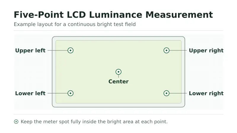
For a graphic LCD that can show a continuous bright field, a center point and four points near the corners can work for an initial comparison. On a positive character LCD, agree which bright background areas to measure. On a negative segment LCD, select lit segments that are large enough for the meter’s measurement spot to fit inside. Keep the spot within the agreed bright area at each point.
The table shows an illustrative measurement with the same LCD, current, pattern, and viewing direction before and after installing the window. All luminance readings are in cd/m².
| Measurement stage | Center | Upper left | Upper right | Lower left | Lower right | Uniformity (min ÷ max) |
| LCD module before window installation | 120 | 112 | 109 | 104 | 100 | 83.3% |
| LCD module with window installed | 102 | 94 | 90 | 85 | 82 | 80.4% |
If the project calls for at least 90 cd/m² at every agreed point, the installed center meets the requirement and the two lower points fall short. Compare those points with the module baseline, then look for variation in the window tint or any masking from the bezel. Run the separate ambient-light test as well. Reflections from the window can make a display harder to read even when its measured luminance meets the agreed target. Information Display’s guide to outdoor industrial displays
How to Choose the Backlight Color and Structure
Match the LED Color to the LCD Mode
Positive and negative describe the appearance of the image. A positive display typically has dark characters on a brighter background. A negative display typically has bright characters on a darker background when illuminated. The same white backlight can therefore produce two quite different looks. The LCD mode, polarizers, LED color, and window tint all contribute to what the operator sees.
White is a practical starting point for a neutral instrument display. Yellow-green is common on classic monochrome character modules. Amber is an option when the display needs to match an established panel appearance. Approve the color with the actual LCD and window in place. If an existing product has a defined appearance, provide a reference sample or an agreed color tolerance and say under which lighting condition it will be judged.
The cover pairs our LCM1602B 16×2 character LCD module with a white LED backlight. When specifying a version, confirm the LCD mode, polarity, and viewing direction together with the LED color. Use the forward voltage and current ratings for the chosen backlight when sizing the drive circuit. Longtech LCM1602B datasheet
Compare Edge-Lit and Direct-Lit Backlights
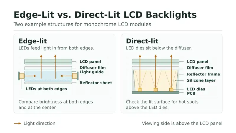
An edge-lit backlight feeds LED light into the side of a light guide. The guide spreads the light across the display area. A reflector and diffuser can help redirect and smooth the light. This arrangement is worth evaluating when the space behind the LCD is limited. Check for a bright band near the LED edge and a falloff on the far side. Texas Instruments’ introduction to display backlighting
A direct-lit backlight places LEDs behind the viewing area. LED spacing, the distance to the diffuser, and the optical stack influence how visible individual bright spots are. Evaluate both layouts against the available depth and the agreed uniformity target. Review where the leads or flex tail exit and how the bezel covers the edges of the lighted area. These details determine whether the backlight fits and whether light is visible through gaps around the window. Hantronix’s LCD module construction guide
How to Drive and Dim an LED LCD Backlight
Read the Backlight Pins and Electrical Ratings
On the 16-pin parallel version of our LCM1602B, the drawing lists three different functions that matter during bring-up. Other module variants may label the backlight pins A and K for anode and cathode. Use the pinout for the exact interface and module version you are buying. Longtech’s 1602 LCD pinout guide
| LCM1602B signal | Pin | Function |
| VDD | 2 | LCD logic supply, nominally 5 V for this version |
| V0 | 3 | LCD contrast adjustment input |
| LED+ and LED− | 15 and 16 | Backlight anode and cathode |
In the backlight specification, look for the forward voltage (V_F) at a stated current, the forward current (I_F) for normal operation, and any current limits over temperature. Check whether the pins lead directly to the LED string or to a circuit with a built-in resistor or driver. If the drawing shows several LEDs in series, size the drive circuit for the forward voltage of the whole string. For parallel strings, ask how current is limited or regulated in each branch.
If the LCD logic runs from 5 V, that tells us which rail supplies VDD. The backlight circuit diagram and ratings tell us whether the same rail can also supply the LEDs and how their current will be set.
Choose a Series Resistor or a Constant-Current Driver
A resistor can be a reasonable choice for a single LED string and a stable supply. Start with R ≈ (V_S − V_F) ÷ I_F, where V_S is the supply voltage. If a switch or another component sits in series, subtract its voltage drop from the voltage available across the resistor. Recalculate the current for the supply limits, the LED forward-voltage range over the relevant conditions, and the resistor tolerance. ROHM’s LED circuit configuration guide
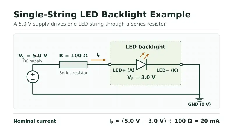
Consider a hypothetical module with a single LED string wired directly to its terminals. Assume a 5.0 V supply with a ±5% tolerance, a nominal 3.0 V string forward voltage, and a target of 20 mA. The nominal calculation gives 100 Ω. The table estimates the current range using a string forward voltage of 2.8 to 3.2 V and a resistor tolerance of ±1%.
| Condition | Calculation | Estimated current |
| Low supply, high forward voltage, high resistance | (4.75 V − 3.2 V) ÷ 101 Ω | 15.3 mA |
| High supply, low forward voltage, low resistance | (5.25 V − 2.8 V) ÷ 99 Ω | 24.7 mA |
At the high-current corner the resistor would dissipate about 61 mW. Check its power rating at the expected board temperature. If the LED’s maximum allowed current under those conditions is 20 mA, the 100 Ω choice needs revisiting. We would either recalculate the resistor and verify luminance at the low-current corner, or use a suitable current regulator. Use the actual LED data and verify the result on a sample because forward voltage varies with current and temperature.
A constant-current driver is worth evaluating when LED current needs to stay stable across variations in supply or string voltage. Verify that the driver can reach the highest expected string voltage with its required headroom. For a low-voltage battery driving several LEDs in series, a boost driver may be needed. Review the driver’s current setting and check the input power budget at the system level. Texas Instruments’ backlight driver overview
Set the Dimming Range
With direct PWM dimming, the LED is switched on and off. For rectangular pulses, the average LED current is approximately the on-current multiplied by the duty cycle. Check the on-current against the applicable current rating at the chosen pulse width, duty cycle, and temperature. With analog dimming, the driver reduces the LED current itself. Check the driver’s output mode because a PWM control input can also be used to command analog dimming. Texas Instruments’ LP8556 datasheet · Texas Instruments’ TPS61165 datasheet
For a panel with day and night settings, define the lowest brightness that is comfortable to read. Test the transition between dimming levels and check for visible flicker at the lowest settings. If a camera will routinely read the screen, check for banding at the intended exposure settings. Choose a PWM frequency within the driver’s specifications, then test it in the finished equipment. IEEE Standards Association white paper on camera performance and LED flicker
How to Validate the Backlight in the Finished Product
Establish a Bench Baseline
Test a sample of the exact LCD and backlight configuration you plan to buy. Log the part number and revision, the test pattern, the viewing direction, the supply voltage, and the LED drive conditions. If dimming is active, record the on-current and duty cycle where applicable. Take luminance readings after the assembly has stabilized and record the temperature and the agreed measurement points.
Check the low and high supply limits and the operating temperatures relevant to the application. At each condition, confirm that the backlight starts, that the current is within the specified range, and that the LCD image is readable. If a cold sample looks faint, check LED current and LCD contrast separately. Those readings help determine whether to investigate the backlight driver or the LCD bias and optical behavior.
Check Readability Through the Enclosure Window
Install the production window, bezel, and any gasket or mask that can affect the view. Put the product in its normal mounting orientation and use representative content, including digits and icons near the edges. If the product is used in bright conditions, record the illuminance at the display plane and the light direction. Then check the same content from the expected operator positions. Test the lowest intended brightness in the dark as well.
| Check | Conditions to record | What to agree for approval |
| Luminance and uniformity | Window installed, temperature, LED drive, bright test pattern, viewing direction, and meter positions | Minimum luminance at agreed points and the uniformity calculation and limit |
| Readability and appearance | Actual screen content, operator angles, ambient light levels, and day or night dimming settings | Required digits and icons are legible. Edge glow, reflections, and bright spots meet the agreed visual criteria. |
| Current and power | Supply limits, temperature, dimming levels, and typical backlight on-time | LED current stays within the agreed range. The system meets its power budget. |
| Start-up and dimming | Power-up at temperature limits and transitions between specified brightness levels | The backlight starts reliably and meets the agreed minimum brightness and flicker requirements. |
For a replacement LCD, run the same checks on the existing unit and the proposed sample under the same conditions. This gives purchasing and engineering a side-by-side basis for comparing appearance, current draw, and fit.
LCD Backlight Specification Checklist for OEMs
A quote is easier to evaluate when each supplier has the same optical, electrical, and mechanical requirements. Use the table below as a starting point for an RFQ or drawing review. If you have an existing display, include its complete part number or datasheet and a photo showing its installed appearance.
| Area | What to include in the RFQ |
| LCD configuration | Character format, graphic resolution, or segment drawing. Include the optical mode, polarity, and preferred viewing direction. |
| Backlight appearance | LED color, minimum luminance at the agreed measurement plane, uniformity limit and calculation, and any reference sample for color matching. |
| Electrical interface | Available supply range, current budget, connector and polarity, and who provides current limiting or the LED driver. Include the required dimming range and control interface. |
| Mechanical fit | Viewing area, overall envelope and maximum depth, LED lead or FPC exit, and a drawing of the window and bezel. Specify any tint or surface treatment. |
| Use conditions | Operating temperature, expected ambient light and viewing angle, typical on-time, and whether the display is dimmed or turned off between readings. |
| Sample approval | The module configuration to qualify, measurement points, test pattern, drive conditions, and criteria for optical and electrical acceptance. |
If your brightness target is still open, share the enclosure drawing, lighting conditions, and available power. We can review which standard or custom monochrome LCD configurations are worth sampling for the application. Discuss your display project with Longtech
LCD Backlight FAQs
Can I power the LCD backlight from the same 5 V supply as the module?
Yes, if the selected backlight circuit supports the rail’s actual voltage range and the supply has enough current capacity. For LED terminals that connect directly to the string, provide the specified current limiting or regulation. If the module has an onboard resistor or driver, follow the input rating for that version. Check the backlight circuit and the module logic supply separately when approving the schematic.
Why does the backlight turn on while the LCD shows no characters?
The LED circuit can be working while the display circuit still needs attention. Check VDD and ground first. On a parallel character module such as the LCM1602K, then check V0, the interface wiring, and the initialization sequence. A correctly illuminated screen can look blank when the contrast setting or the controller setup is incorrect.
Can I reduce backlight current and keep the display readable?
Often, especially for a panel that is mainly read indoors or has a separate night setting. Reduce the current within the operating range of the LED and driver, then measure the installed screen at that setting. Check the most difficult viewing angle and the brightest expected surroundings. For a transflective meter, also test daylight readability with the LEDs off. Those results show which brightness levels the product can use in each operating mode.
